| View previous topic :: View next topic |
| Author |
Message |
Jenova
Interesat
Joined: 14 Oct 2006
Posts: 22
|
 Posted: Sun Oct 15, 2006 3:00 am Post subject: Posted: Sun Oct 15, 2006 3:00 am Post subject: |
 |
|
well, i tried on another machine and it still gives me the same error: eeprom not avaliable. makes me think that i need to test the volts on the serial port and on the wires that i soldered onto the atmel chip. is there any certain way to test the power coming from the atmel chip? thank you so much everyone.
_________________
myspace.com/ninemonthfall <-- contact me
-shane-nmf- |
|
| Back to top |
|
 |
victor
S.F. Boss

Joined: 07 Mar 2004
Posts: 2581
Location: Staff
|
 Posted: Sun Oct 15, 2006 9:08 am Post subject: Posted: Sun Oct 15, 2006 9:08 am Post subject: |
 |
|
I saw the pictures and and the pins are correct and I hope the wries are in good contact with the pins.
1. Running itester, check the SDA&SCL voltages.
SCL: 5.1V (1), -0.6V (0)
SDA: ~3.3V (1), -0.6V (0)
The SDA voltage will be a bit lower than SCL's.
2. G40 shuted down. Check with an ohmeter the eeprom's SDA and SCL pins impedance against GND and VCC. In fact GND is pin #4 and VCC in pin #8, so you have to see how many Kohms are between those and pins #5 and #6 (which are SDA and SCL).
You can avoid doing all these experiements at anytime, if you build the driven programmer, you know. |
|
| Back to top |
|
 |
Jenova
Interesat
Joined: 14 Oct 2006
Posts: 22
|
 Posted: Sun Oct 15, 2006 9:26 pm Post subject: Posted: Sun Oct 15, 2006 9:26 pm Post subject: |
 |
|
i think i will build the driven programmer. i guess ill have to order some parts online. i cant seem to find anywhere that sells the max232 chip to the general public. they all want to sell in bulk. ill look around for the extra parts and get back with you after i complete the driven circuit. thank victor for your answers and for being so patient with me. be back in about a week!
-shane-nmf-
_________________
myspace.com/ninemonthfall <-- contact me
-shane-nmf- |
|
| Back to top |
|
 |
victor
S.F. Boss

Joined: 07 Mar 2004
Posts: 2581
Location: Staff
|
 Posted: Sun Oct 15, 2006 10:50 pm Post subject: Posted: Sun Oct 15, 2006 10:50 pm Post subject: |
 |
|
| Ok. A propos, nice music, congratulations! |
|
| Back to top |
|
 |
Jenova
Interesat
Joined: 14 Oct 2006
Posts: 22
|
 Posted: Tue Oct 24, 2006 5:30 am Post subject: Posted: Tue Oct 24, 2006 5:30 am Post subject: |
 |
|
well, i had to drive a long way, but i finnally have the parts i need to build the driven circuit. i have a few questions before i hook it all up.
the chip i have is not a genuine "max232a" chip. so my first question is : do companies make generic max232a chips? heres a pic of the chip i bought placed on the breadboard:

secondly, from what i can read on the forum here, capacitors come in two verieties. some require positive and negitave pins, while the other doesnt matter which way it is plugged into the breadboard. the capacitors i have are 0.1 uF polyester film capacitors. does it matter which way they are plugged into the breadboard?
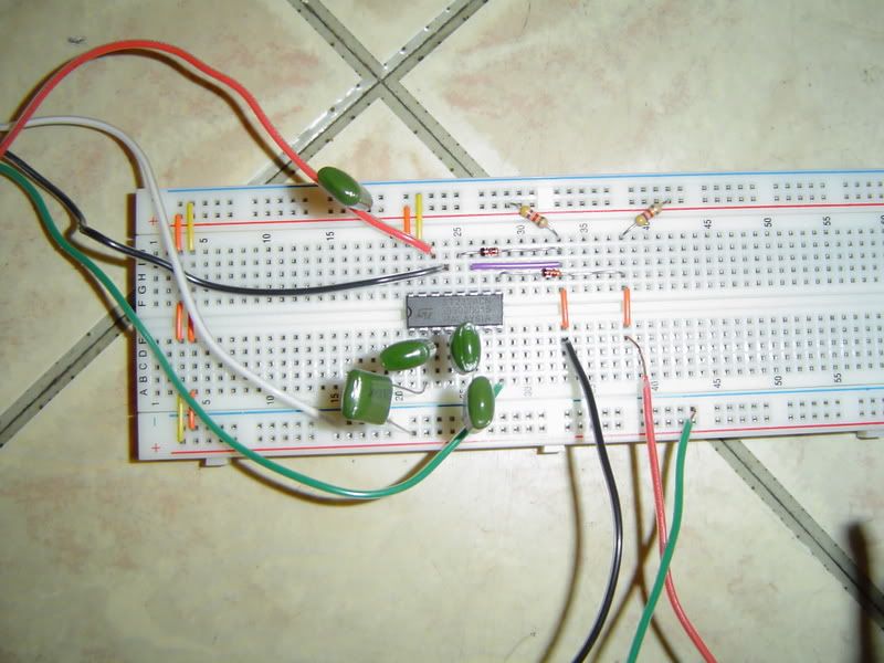
and finnally, here is a pic of my breadboard set up:

is anything out of order? thanks so much guys!
-shane-nmf-
_________________
myspace.com/ninemonthfall <-- contact me
-shane-nmf- |
|
| Back to top |
|
 |
Jenova
Interesat
Joined: 14 Oct 2006
Posts: 22
|
 Posted: Tue Oct 24, 2006 5:32 am Post subject: Posted: Tue Oct 24, 2006 5:32 am Post subject: |
 |
|
oh yeah, one more thing. where do i plug the 4 battery power supply at on the breadboard? the left side of the board or the right?
_________________
myspace.com/ninemonthfall <-- contact me
-shane-nmf- |
|
| Back to top |
|
 |
victor
S.F. Boss

Joined: 07 Mar 2004
Posts: 2581
Location: Staff
|
 Posted: Tue Oct 24, 2006 10:38 am Post subject: Posted: Tue Oct 24, 2006 10:38 am Post subject: |
 |
|
The breadboard looks ok.
Black=SDA
Red= SCL
Green= GND.
I can't see the IC, you said is a clone of max232A. Which one exactly?
[EDIT] I see it now, ST232ACN.
Your capacitor are not polarized, doesn't matter how you plugged them into the breadboard. But try to cut their legs as short as you can, trust me.
Normaly, you need a 3AA battery holder. I understand that you followed Ray Kawakami's design, but I guess he had only 4 battery holders and needed to improvise a bit to get the job done.
Try with itester and see how it's working. Invert box must be checked. |
|
| Back to top |
|
 |
Jenova
Interesat
Joined: 14 Oct 2006
Posts: 22
|
 Posted: Tue Oct 24, 2006 6:46 pm Post subject: Posted: Tue Oct 24, 2006 6:46 pm Post subject: |
 |
|
thanks for the tip for the capacitors. well, ive tried this circuit with itester before and when i checked the "invert" box the two values changed from:
1
0
then:
1
1
so i think i need to cut the capacitors legs like you said and try again. its supposed to be 1,1 and 0,0 right? also, will my max clone chip need different uF capacitors, or will the ones i have work? one more question : i am using a really dead AA battery to complete the 4 AA holder. do you think that will be a problem?
_________________
myspace.com/ninemonthfall <-- contact me
-shane-nmf- |
|
| Back to top |
|
 |
victor
S.F. Boss

Joined: 07 Mar 2004
Posts: 2581
Location: Staff
|
 Posted: Tue Oct 24, 2006 7:31 pm Post subject: Posted: Tue Oct 24, 2006 7:31 pm Post subject: |
 |
|
After a short period of 10 seconds, the valuses must be 1,1 -0,0- 1,1 and so on. If you chaeck with a voltmeter, you should have 4-4.5V when 1.
| Quote: | | I am using a really dead AA battery to complete the 4 AA holder. do you think that will be a problem? |
Are you jokeing, right? Use 3 AA batteries only! |
|
| Back to top |
|
 |
Jenova
Interesat
Joined: 14 Oct 2006
Posts: 22
|
 Posted: Wed Oct 25, 2006 7:26 am Post subject: Posted: Wed Oct 25, 2006 7:26 am Post subject: |
 |
|
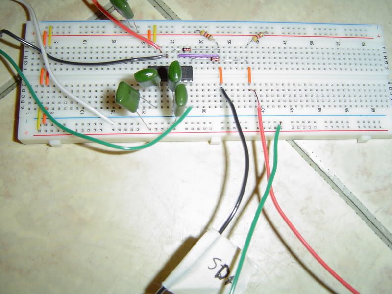
ok, i cut down the capacitors and hooked everything up. im still getting the same results from the itester. i gave it a try anyway and r24rf08 is saying circuit not found. im going to check to make sure i built it right. here is a pic:

_________________
myspace.com/ninemonthfall <-- contact me
-shane-nmf- |
|
| Back to top |
|
 |
The_WishMasteR
Interesat
Joined: 15 Oct 2006
Posts: 15
|
 Posted: Wed Oct 25, 2006 10:15 am Post subject: Posted: Wed Oct 25, 2006 10:15 am Post subject: |
 |
|
hello there i'm geting the exact same problem as you but i don't use the baterys, cuse they are only necessary if you unsolder the EPROM from the laptop, if thats the case sory or if i'm wrong some one please correct me, but geting to the probleme again i am going to make what victor told me to do thats to buy some electrolyt capacitors they are smaler and it's easy to set up as well and rebuild every thing from scratch and try again, if you can succeed before i do please tell me what you did.
greatings to all |
|
| Back to top |
|
 |
victor
S.F. Boss

Joined: 07 Mar 2004
Posts: 2581
Location: Staff
|
 Posted: Wed Oct 25, 2006 1:51 pm Post subject: Posted: Wed Oct 25, 2006 1:51 pm Post subject: |
 |
|
| You need the batteries to power the driven programmer! |
|
| Back to top |
|
 |
The_WishMasteR
Interesat
Joined: 15 Oct 2006
Posts: 15
|
 Posted: Wed Oct 25, 2006 5:27 pm Post subject: Posted: Wed Oct 25, 2006 5:27 pm Post subject: |
 |
|
| victor wrote: | | You need the batteries to power the driven programmer! |
so what you are saying is i have to have the bateries even if i dont unsolder the eprom?
and another thing i just received the capacitors but i cant teel wich one is the + wich one is the - can you tell me i noticed one leg is shorter than the other but can you tell me wich one is wich? |
|
| Back to top |
|
 |
victor
S.F. Boss

Joined: 07 Mar 2004
Posts: 2581
Location: Staff
|
 Posted: Wed Oct 25, 2006 6:14 pm Post subject: Posted: Wed Oct 25, 2006 6:14 pm Post subject: |
 |
|
Did you plan to kill me, right? 
Ok, I wonder how do they look like?! What makes them so special 
Last edited by victor on Wed Oct 25, 2006 6:30 pm; edited 1 time in total |
|
| Back to top |
|
 |
The_WishMasteR
Interesat
Joined: 15 Oct 2006
Posts: 15
|
 Posted: Wed Oct 25, 2006 6:22 pm Post subject: Posted: Wed Oct 25, 2006 6:22 pm Post subject: |
 |
|
| victor wrote: | Did you plan to kill me, right? 
Ok, I wonder how they look like?! What makes them so special  |
Sorry but i didn't understand what you are saying  i relly don't i relly don't
please victor help out a newb  |
|
| Back to top |
|
 |
|


