 |
Service Forum
support board, PC repair, unlocking solutions
|
| View previous topic :: View next topic |
| Author |
Message |
rocky
Nou Venit
Joined: 14 Dec 2007
Posts: 4
|
 Posted: Fri Dec 14, 2007 7:26 am Post subject: Another G40, SI-PROG circuit check, if you would [Solved] Posted: Fri Dec 14, 2007 7:26 am Post subject: Another G40, SI-PROG circuit check, if you would [Solved] |
 |
|
Hi all you friendly and much more knowledgeable people than I 
Like the title says, I'm working on unlocking a TP g40 and I've had to rip apart the whole thing (ATMEL chip turned out to be on the underside of the MB, handy, eh?). Anyway, I've hooked everything up, crossed my fingers and of course, something went wrong.
I got this error message:
| Quote: | Initializing timer...13732 OK
ERROR: Eeprom not available! |
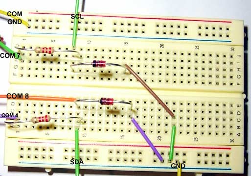
So, my first thought is that I built the circuit wrong, here's what I have going on, it is of course the simple circuit, by the way:

(Sorry about the picture quality, my camera isn't the best and I know I should trim down the resistors and the diodes, but I didn't think it would affect it too much)
So, if anyone would be so kind to tell me how horribly wrong it may be (it's been quite awhile since physics, so be kind!  ) I would really appreciate it. ) I would really appreciate it.
I looked around on the forum for a picture of the simple circuit completed but it appears that the images were all dead references (just my luck, haha)
EDIT:: Spelling..gah!  |
|
| Back to top |
|
 |
victor
S.F. Boss

Joined: 07 Mar 2004
Posts: 2581
Location: Staff
|
 Posted: Fri Dec 14, 2007 1:24 pm Post subject: Posted: Fri Dec 14, 2007 1:24 pm Post subject: |
 |
|
Hello,
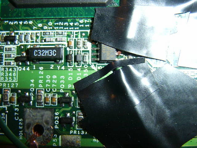
The circuit looks quite good and, moreover, is correct. The only part I didn't see here is the COM connector, but I guess that is correct too, if I refer strictly to the error showed up. However, a picture with the eeprom pins would be useful
I give you a short list of possible issues:
i. You connect it to the wrong eerprom pins.
ii. Zeners are having a wrong value (often the guy form the store is an idiot or he's doing it on purpose).
S: You can perform an interface check using itester and see the outputs voltage.
iii. The port is too "weak" to sustain the eeprom signals.
S: Try it on another PC
iv. Mirrored COM port connections (like hooking up the wires to the wrong pin numbers, quite in oposition)
v. and more..
Nevertheless, if you would choose to build up the driven programmer, the major part of the above problems would not have been funded.
First action is to check it with itester. I've already explained in various posts how to do it, besides the program has a help window. What is important is that SDAin and SDA/SCL out must be identical all the time. Please also note the SCL and SDA voltage for each TTL state 1 and 0
Good luck!
_________________
Victor Voinea
ALLservice HQ, Romania. |
|
| Back to top |
|
 |
rocky
Nou Venit
Joined: 14 Dec 2007
Posts: 4
|
 Posted: Sat Dec 15, 2007 5:18 am Post subject: Posted: Sat Dec 15, 2007 5:18 am Post subject: |
 |
|
Thank you sir for the help and insight and sorry about the delay, I hate to leave my projects half finished, especially when they are covered in plastic wrap to keep the dust off, but with the holidays comes holiday duties and so many things to be done, haha.
Anyways, back to business, I didn't build the driven programmer because I don't trust my circuit building abilities on a more complex project nor do I trust my component finding abilities  . .
As for the circuit I have here, a part of me is glad that the circuit is correct, but then another part is dreading the meaning that it isn't as simple a solution as flipping a diode, two sides to everything I suppose...
I've done the checking with the itester and a multimeter and both values are identical and switch together, however I'm getting some strange values for the voltages that perhaps some light can be shed on:
SDA(0) = +3.27
SDA(1) = -.67
SCL(0) = -.67
SCL(1) = +3.27
So, (from my limited understanding, anyway) the high voltages are a little low and SDA seems to be reversed, I thought the voltages might be fault of the com port on the box as you had mentioned com port difficulties, so I tried it on another with the same results, but that doesn't mean the other's com port isn't the same, so not really a difinitive test at all, I suppose... I did, however, check the voltages coming in from the port into the circuit and they were all in the 10 ~ 11 range, if that is informative at all.
I've also done some continuity testing on all my wires, I wanted to specifically check the wires connected to the chip, as I did not trust my hand not to fry the chip or solder two pins together, I've used tape, but my multimeter says they are making the connection.
Here's a picture of the eeprom and pins, not sure how much you can make out with all the tape (sorry about that), but I didn't want to move too much off once I had done the connection testing, but if you'd like one without all the tape to see better I'll take it off and take another one right quick like.

As for the zeners, I didn't trust one of the store grunts to go get me one, so I just headed to the back of RadioShack and picked them up, I'm pretty certain they are the proper ones as they have the 5.1V zener diode printed on the package the part number is: 1N4733A
Alright, I think that is all, but knowing me, I'll think of something else right after I've posted |
|
| Back to top |
|
 |
victor
S.F. Boss

Joined: 07 Mar 2004
Posts: 2581
Location: Staff
|
 Posted: Sun Dec 16, 2007 10:41 pm Post subject: Posted: Sun Dec 16, 2007 10:41 pm Post subject: |
 |
|
Well, I gotta say you should ran itester without the SDA and SCA connected to the eeprom or the data may be damaged. If the above values are resulted from such manouver, the test is not concludent.
_________________
Victor Voinea
ALLservice HQ, Romania. |
|
| Back to top |
|
 |
rocky
Nou Venit
Joined: 14 Dec 2007
Posts: 4
|
 Posted: Mon Dec 17, 2007 7:18 am Post subject: Posted: Mon Dec 17, 2007 7:18 am Post subject: |
 |
|
Oh, I apologize, I should have been more specific in my information.
Both the itester and multimeter values were obtained with the SDA, SCL, and GND (chip, not COM) wires unconnected to the eeprom. When testing the voltages I would hook onto the SDA or SCL wire and also the GND wire.
Thanks for the warning, though.
Any ideas on my odd voltages? |
|
| Back to top |
|
 |
victor
S.F. Boss

Joined: 07 Mar 2004
Posts: 2581
Location: Staff
|
 Posted: Tue Dec 18, 2007 2:30 am Post subject: Posted: Tue Dec 18, 2007 2:30 am Post subject: |
 |
|
I think I want to see the COM port connections, a picture with the DB9 female if possible.
[Edit]
Looking again at your circuit, is something that I missed: -How did you connect the COM's GND to the anodes? I don't see a wire between the upper GND to the lower GND in your breadboard... or is just me
_________________
Victor Voinea
ALLservice HQ, Romania. |
|
| Back to top |
|
 |
rocky
Nou Venit
Joined: 14 Dec 2007
Posts: 4
|
 Posted: Tue Dec 18, 2007 7:52 am Post subject: Posted: Tue Dec 18, 2007 7:52 am Post subject: |
 |
|
Never before have I been so thrilled to have improperly interpreted a circuit! That was it, connected it properly, was reading as 4.66 on the high and -.79 on the low...not exact, but it was enough, apparently!
Read it in off the eeprom and now I can finally use the thing.
Thank you, sir, without all of the information here and your input, there would have been no way I would have been able to use the TP.
Is there anything I can do to help the people here, I noticed in some posts that the dump files are requested, would you be interested in having my g40's dump?
Thanks again! |
|
| Back to top |
|
 |
victor
S.F. Boss

Joined: 07 Mar 2004
Posts: 2581
Location: Staff
|
 Posted: Tue Dec 18, 2007 2:42 pm Post subject: Posted: Tue Dec 18, 2007 2:42 pm Post subject: |
 |
|
You're welcome, its always a pleasure to give you a little help if I could do it. I also apologize for the late replies.
Maybe you may come back here from time to time and share your experience to someone who needs help, I would really appreciate that.
And yes, we never refuse a dump, you may send it to our support=at-allservice.ro
_________________
Victor Voinea
ALLservice HQ, Romania. |
|
| Back to top |
|
 |
|
|
You cannot post new topics in this forum
You cannot reply to topics in this forum
You cannot edit your posts in this forum
You cannot delete your posts in this forum
You cannot vote in polls in this forum
|
|


